Language:

How to Choose the Right RF Coaxial Connector?

Choosing the right RF Coaxial Connector is not a minor purchasing decision. It directly affects signal integrity, equipment safety, and long-term reliability.

Howard Johnson, a respected signal-integrity engineer, famously said, “The signal does not know what you intended; it only knows what you built.” That principle applies strongly to RF assemblies. A connector may look precise, yet poor impedance control can create reflections, insertion loss, and unstable measurements. Small details matter.

Begin with the operating frequency and required impedance. Most RF systems use 50-ohm connectors, while some video applications use 75-ohm designs. SMA, N-type, BNC, TNC, and MMCX connectors each serve different electrical and mechanical needs. Frequency ratings should come from verified manufacturer data, not appearance or price.

Think about the real installation. A laboratory SMA connector may suit a clean test bench, but an outdoor N-type connector offers better protection against moisture and vibration. Check cable size, mating cycles, plating material, torque requirements, and environmental sealing. A connector that fits physically may still perform poorly electrically.

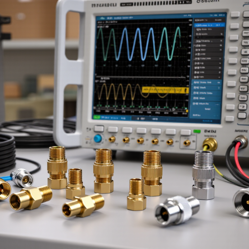
Testing remains essential. Use a calibrated vector network analyzer when possible. Measure return loss and insertion loss across the actual operating band. Inspect the center pin and dielectric for damage. It takes seconds.

There is no perfect connector for every system. Even experienced engineers can overlook cable flexibility, assembly quality, or repeated mating stress. I have seen reliable designs fail because one connector was tightened by feel instead of specification. Careful selection combines datasheets, practical installation experience, and measured performance. That is the foundation of a dependable RF Coaxial Connector choice.

How to Choose the Right RF Coaxial Connector?

RF Coaxial Connector Basics and Key Performance Terms

How to Choose the Right RF Coaxial Connector?

RF coaxial connectors transfer high-frequency signals through a controlled electromagnetic path. The basics matter: impedance, frequency range, return loss, insertion loss, and shielding effectiveness. Most systems use 50-ohm impedance, while broadcast video commonly uses 75 ohms. Mixing them can create reflections.

Small errors become expensive.

The Ericsson Mobility Report, November 2024, forecasts more than 6 billion 5G subscriptions by 2030. This growth increases demand for connectors that remain stable at higher frequencies. Check the connector’s specified bandwidth before choosing it. Then compare VSWR, which describes reflected energy, and return loss, which expresses matching quality in decibels. Higher return loss usually means better performance. Insertion loss should remain low, especially across long cable assemblies. Do not ignore passive intermodulation, or PIM, in dense wireless installations. Tiny contact imperfections can generate unwanted signals.

Mechanical details also influence reliability. Review mating cycles, cable retention, vibration resistance, operating temperature, and ingress protection. A connector may perform well in a laboratory but fail near moisture, dust, or repeated movement. Industry testing guidance, including IEC 61169 requirements, helps define measurable interface performance. Still, datasheets do not reveal everything. Installation torque, cable routing, and connector cleanliness deserve practical testing. I have seen a technically excellent connector underperform after careless assembly. Selection should match the complete system, not just the highest advertised frequency.

Identify the Required Frequency, Impedance, and Power Ratings

How to Choose the Right RF Coaxial Connector?

Frequency is the first filter. A connector rated for 6 GHz may perform poorly at 18 GHz. Check the upper operating frequency, not only the system’s nominal band. The 2024 Ericsson Mobility Report forecasts continued growth in 5G traffic and wider use of millimeter-wave networks. That trend makes high-frequency loss and reflection harder to ignore. For each candidate, compare insertion loss, return loss, and VSWR at the highest working frequency. Small mechanical gaps can become serious electrical discontinuities.

Impedance must match the complete signal path. Most RF systems use 50 ohms, while many video systems use 75 ohms. Do not mix them casually. A 50-ohm connector joined to a 75-ohm cable can create reflections, even when the parts physically fit. IEC 61169 test methods provide a useful framework for connector performance, but the actual datasheet remains decisive. Verify the interface, cable type, and calibration setup together.

Power ratings require more judgment. Published values often assume a specific frequency, ambient temperature, duty cycle, and standing-wave ratio. The 2023 MarketsandMarkets RF connector analysis reports expanding demand across wireless infrastructure and test equipment, where thermal margins vary widely. Derate the rating when temperature rises or VSWR increases. Peak power is not continuous power. I have seen selections fail because engineers trusted one impressive number. Check average power, peak voltage, and connector heating. Then question the result. Short-term testing can hide long-term stress.

Compare Connector Types, Interfaces, and Mounting Methods

Choosing the right RF coaxial connector starts with the signal, not the shape. An RF connector must match the cable impedance, frequency range, power level, and available space. A 50-ohm system should not use a 75-ohm connector casually. Small threaded connectors suit compact equipment and stable laboratory setups. Bayonet-style connectors allow faster repeated access. Snap-on types save time, but they may loosen under vibration.

The interface affects electrical and mechanical reliability. Check the contact design, mating tolerance, and plating quality. A smooth connection is not always a good connection. Poor alignment can increase signal loss and reflection. I once selected a connector by size alone, then noticed unstable readings above the intended frequency. That mistake was avoidable.

Mounting method deserves equal attention. PCB connectors need controlled footprints and strong board support. Panel connectors require a firm locknut and enough clearance for tools. Bulkhead versions work well when a cable must pass through an enclosure wall. Cable-mounted connectors offer flexibility, but correct stripping and crimping are critical. Solder joints can look acceptable while hiding weak shielding. Measure the finished assembly when possible. For outdoor or mobile equipment, inspect sealing, strain relief, and vibration resistance. A connector may meet its datasheet limits yet fail in a real enclosure because the cable bends too sharply. The best choice is the one that fits the interface, mounting method, and actual working conditions.

Match Materials, Environmental Conditions, and Mechanical Requirements

Choosing the right RF coaxial connector begins with its working environment, not its appearance. Material selection affects conductivity, corrosion resistance, strength, and service life. Plated contacts can reduce oxidation, while stainless steel bodies offer better resistance in humid or salty locations. However, every coating has limits. Check the material specification and mating compatibility carefully.

Temperature cycling, moisture, dust, vibration, and chemical exposure can gradually weaken an otherwise suitable connector. Sealing performance matters outdoors. Use the stated ingress rating as a guide, then consider cable movement and installation quality. A connector may survive laboratory testing but fail after repeated field handling. That possibility deserves attention. Mechanical details also matter: interface type, coupling method, cable diameter, bend radius, panel clearance, and expected mating cycles should match the assembly. Excessive tightening may damage threads or distort the interface. Loose coupling can create intermittent signals.

Tips: Compare the connector’s material, temperature range, sealing method, and mechanical ratings with real operating conditions. Check return loss and frequency limits after cable assembly, not only before installation. Inspect samples under vibration and temperature changes when reliability is critical. Keep a small test record, because memory is not a dependable specification. If technicians need tools or unusual torque procedures, reconsider the design. Simple maintenance usually survives longer.

Verify Compatibility, Installation Needs, and Long-Term Reliability

How to Choose the Right RF Coaxial Connector?

Choosing an RF coaxial connector starts with compatibility, not appearance. Check the cable type, connector interface, impedance, and operating frequency. A 50-ohm connector on a 75-ohm system can create unwanted reflections and signal loss. Confirm the manufacturer’s electrical specifications, including voltage standing wave ratio and insertion loss. Small differences matter at higher frequencies.

Installation conditions deserve equal attention. Measure the cable diameter before ordering, because a loose clamp can weaken the connection. Check whether the connector needs crimping, soldering, or compression tools. I once selected a connector with the correct interface but ignored the cable’s outer jacket thickness. The assembly looked neat, yet it pulled loose during testing. That mistake was avoidable.

Think about service life, too. Review mating-cycle ratings, temperature limits, moisture protection, and corrosion resistance. In outdoor equipment, sealing details can matter more than a low purchase price. Use the specified tightening torque, maintain the cable’s bend radius, and add strain relief where movement is likely. Do not rely on hand-tightening alone. It feels sufficient, but it may produce unstable performance. Test the finished assembly for continuity, return loss, and mechanical security before deployment. Recheck it after vibration, thermal changes, or repeated maintenance.

How to Choose the Right RF Coaxial Connector? – Verify Compatibility, Installation Needs, and Long-Term Reliability

Connector Family Typical Impedance Typical Frequency Capability Mating and Locking Method Installation Requirements Cable and Interface Compatibility Environmental and Reliability Considerations Compatibility Checks Before Purchase
SMA Normally 50 ohms Commonly DC to 18 GHz; precision versions may support higher frequencies Threaded coupling; typically tightened with a wrench to the specified torque
  • Requires rotational clearance for threading
  • Use the correct torque to protect the interface
  • Suitable for panel, cable, and PCB mounting
Available for semi-rigid, flexible, hand-formable, and PCB applications; interface dimensions must match Good mechanical retention and vibration resistance when correctly torqued; weatherproof versions require a suitable gasket or sealing method Confirm impedance, gender, thread type, cable size, center-contact dimensions, and rated frequency
Type N 50 ohms or 75 ohms versions Commonly DC to 11 GHz; the exact rating depends on the design and impedance Threaded coupling with strong mechanical retention
  • Needs more installation space than miniature connectors
  • Panel mounting is common
  • Use sealing hardware for outdoor installations
Supports larger flexible cables and many low-loss feeder cables; 50-ohm and 75-ohm interfaces are not interchangeable Well suited to outdoor and infrastructure applications when properly sealed; robust against vibration and handling Verify impedance, mating interface, cable diameter, panel thickness, weatherproof rating, and torque specification
BNC 50 ohms or 75 ohms versions Commonly DC to 4 GHz; some precision versions support higher frequencies Bayonet coupling; quick connect and disconnect
  • Requires alignment of the bayonet pins
  • Fast installation where frequent connection changes are expected
  • Allow clearance for the locking sleeve
Available for flexible coaxial cables, test leads, panel mounting, and PCB mounting; cable termination style must match Convenient and reliable for laboratory and instrumentation use; not automatically weatherproof without an appropriate sealed design Check 50-ohm or 75-ohm impedance, gender, cable type, contact termination, frequency rating, and mating-cycle requirements
TNC Normally 50 ohms Commonly DC to 11 GHz; performance varies by construction Threaded coupling derived from the bayonet-style interface family
  • Requires rotational access for tightening
  • Suitable when vibration resistance is more important than rapid mating
  • Panel and cable versions are widely used
Compatible with many flexible coaxial cables and equipment ports designed for the same interface; do not assume interchangeability with BNC Threaded coupling provides better resistance to vibration than a bayonet connection; sealed versions can support outdoor use Verify thread compatibility, impedance, cable diameter, seal construction, mating torque, and operating frequency
SMB 50 ohms or 75 ohms versions Commonly DC to 4 GHz Snap-on coupling; fast and compact
  • Needs limited axial insertion space
  • Useful for internal equipment and PCB assemblies
  • Not ideal where repeated cable movement is expected
Designed for small flexible coaxial cables, PCB mounting, and compact assemblies; cable retention depends on the termination design Compact but generally less mechanically robust than a threaded connector; protect it from excessive pull, bending, and vibration Confirm impedance, snap-on interface, cable size, PCB footprint, orientation, retention force, and environmental rating
MCX 50 ohms or 75 ohms versions Commonly DC to 6 GHz Snap-on coupling
  • Requires very little board and panel space
  • Use strain relief on cable assemblies
  • Allow controlled cable routing to avoid side loading
Commonly used with small-diameter coaxial cables and PCB-mounted equipment; interface size is not interchangeable with SMB Good for compact electronics, but repeated side loading can reduce contact reliability; choose a vibration-rated design when required Check interface family, impedance, cable diameter, PCB footprint, cable exit direction, and allowable bending radius
MMCX Normally 50 ohms Commonly DC to 6 GHz Snap-on coupling with a compact rotating interface
  • Suitable for highly space-constrained PCB designs
  • Use board support and cable strain relief
  • Avoid excessive cable rotation or pulling
Used with miniature coaxial cable assemblies and PCB connectors; cable assembly dimensions and contact style must match Space efficient, but the small interface is sensitive to mechanical abuse; select a tested retention and vibration performance level Verify mating interface, PCB pattern, impedance, cable construction, orientation, retention, and permitted cable movement
7/16 DIN Normally 50 ohms Commonly DC to 7.5 GHz; exact performance depends on the connector design Large threaded coupling with high contact force
  • Requires substantial installation space and correct torque
  • Suitable for high-power feeder and base-station systems
  • Use appropriate cable preparation tools
Designed for large-diameter coaxial cables and high-power RF paths; cable connectorization must follow the cable manufacturer’s preparation dimensions Strong mechanical performance, low passive intermodulation potential when correctly installed, and good outdoor suitability with proper sealing Confirm power level, cable size, impedance, PIM requirement, weatherproofing method, torque, and installation tooling
NEX10-Class Small-Cell Connector Normally 50 ohms Commonly supports frequencies into the 6 GHz range; rating varies by design Threaded coupling designed for high-density radio equipment
  • Requires controlled torque and correct panel alignment
  • Useful where low intermodulation and compact spacing are important
  • Follow the specified connector and cable preparation process
Typically paired with small-cell and distributed-radio cable assemblies; mating geometry and cable interface are application-specific Designed for dense RF systems with demanding mechanical and passive-intermodulation requirements; outdoor sealing depends on the complete assembly Verify mating standard, cable type, PIM performance, frequency range, panel cutout, torque, and sealing accessories
SMP Normally 50 ohms Commonly DC to 26.5 GHz; precision configurations may support higher frequencies Blind-mate, push-on, or limited-detent coupling depending on the version
  • Useful for dense modules and blind-mate assemblies
  • Requires accurate alignment and controlled axial movement
  • Provide mechanical support for connected cables
Used with miniature coaxial cable, PCB launch structures, and board-to-board RF modules; exact interface style must match High-frequency capability and compact size; blind-mate versions require careful alignment to prevent contact damage Confirm coupling style, interface tolerance, impedance, frequency rating, alignment travel, PCB footprint, and mating-cycle target
QMA Normally 50 ohms Commonly DC to 18 GHz; exact rating depends on the construction Quick-lock coupling with axial push-and-turn engagement
  • Requires less rotational clearance than a fully threaded connector
  • Useful for dense equipment panels
  • Use the specified locking procedure to avoid incomplete engagement
Often available for flexible cables and panel assemblies; it is not a universal substitute for SMA despite similar RF applications Provides faster installation than conventional threaded coupling while retaining positive mechanical locking; use sealed hardware for outdoor exposure Check the exact mating interface, impedance, cable size, frequency, locking clearance, seal design, and torque or locking instructions
Selection rule: Always verify the complete assembly—not only the connector name. Confirm impedance, mating interface, frequency range, cable construction, mounting method, power handling, environmental rating, torque, sealing, and the required service life. Published ratings are typical industry ranges and may vary by connector construction, cable assembly, and test conditions.
Member of

Associated Wire Rope FabricatorsMHI MemberNetPlus Alliance Member Steel Erectors Assocation STADFA member

Terms of Sale | Privacy Policy